Rectifier circuit diagram Rectifier bridge diagram circuit wave construction principle working Rectifier circuit diagram
Full Wave Rectifier-Bridge Rectifier-Circuit Diagram with Design & Theory
Full wave bridge rectifier Full wave rectifier circuit diagram (center tapped & bridge rectifier) Rectifier wave bridge circuit diodes operation negative forward becomes figure below its biased
Rectifier wave bridge
Full wave bridge rectifier – circuit diagram and working principleSchematic diagram of full-wave bridge rectifier. Full wave bridge rectifier circuit in multisimRectifier wave bridge circuit operation contents its disadvantages advantages.
Full wave bridge rectifierSi lab Rectifier wave bridge operation half animation input working cycle current positive forward during gif diodes tutorial reverse biased d3 d4Rectifier transformer waveform tapped etechnog.

Full wave bridge rectifier circuit diagram
Rectifier bridge wave animation circuit diagram physics electronicsFull wave bridge rectifier supply Full wave bridge rectifier – circuit diagram and working principleFull wave rectifier-bridge rectifier-circuit diagram with design & theory.
Rectifier wave circuit filter without bridge diagram capacitor tapped diodes center type circuits four board below using circuitdigest electronic chooseFull wave rectifier-bridge rectifier-circuit diagram with design & theory Rectifier wave bridge circuitSimulate full wave bridge rectifier with proteus.

Circuit rectifier bridge wave multisim diagram questions reason anyone point why stack
Rectifier wave bridge current voltage circuit path diagram circuitstoday half flow peak inverse cycleProteus rectifier bridge wave simulate Rectifier wave bridge circuit diagram diode voltage peak operation fig inverse disadvantages advantages value itsBridge wave rectifier circuit output half diagram cycle principle working rectifiers input theory current.
Rectifier circuit diagram wave output waveform inputFull wave bridge rectifier operation Rectifier circuit bridge diagram wave working detailsFunction of resistor in full wave rectifier.

What should i consider when choosing the right diode…
Rectifier bridge wave supply micro diagram digital detailRectifier diode rectifiers circuits Rectifier bridge wave diagram schematic illustration circuitsFull wave bridge rectifier circuit diagram.
Full wave bridge rectifierRectifier bridge wave circuit diagram regulator ic Full wave bridge rectifier.

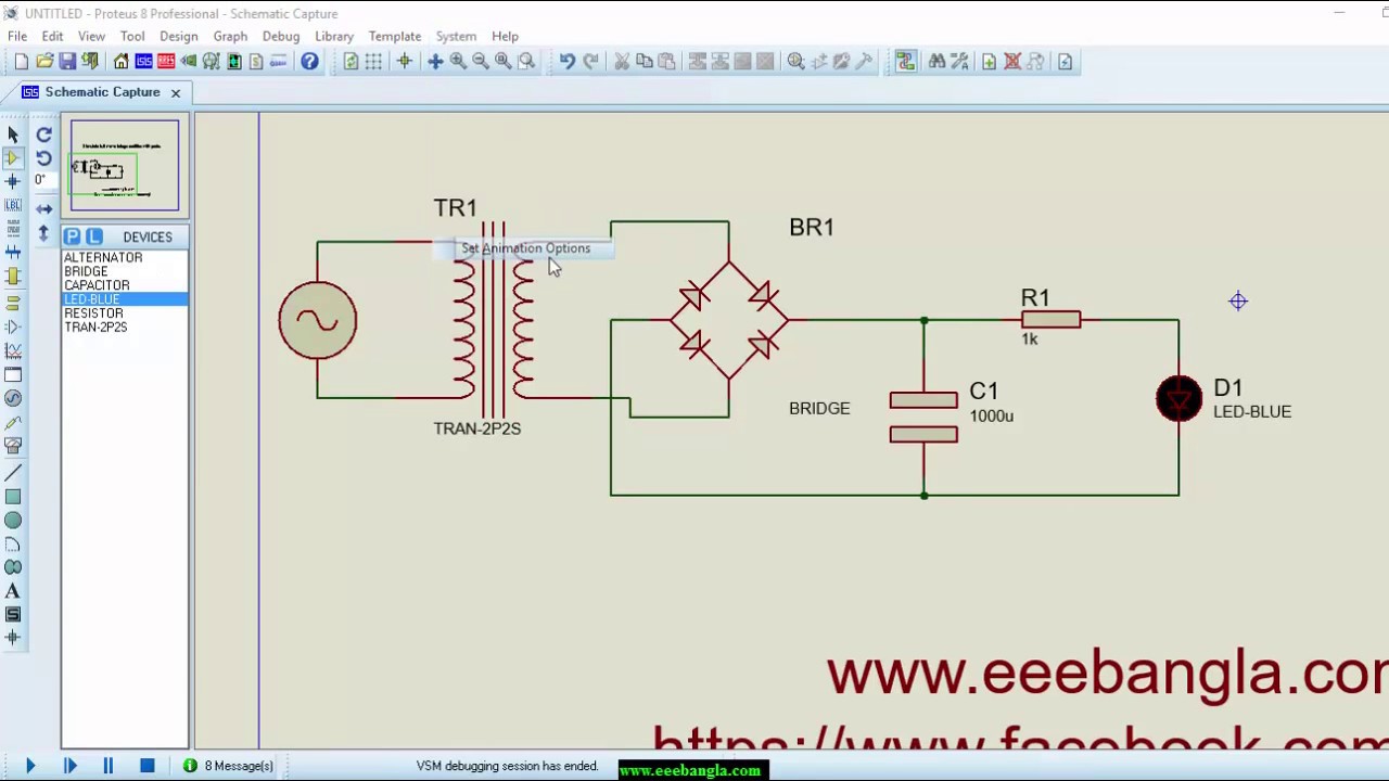
Simulate full wave bridge rectifier with proteus - YouTube

Full Wave Rectifier-Bridge Rectifier-Circuit Diagram with Design & Theory

Full Wave Bridge Rectifier Operation - Engineering Tutorial

Schematic diagram of full-wave bridge rectifier. | Download Scientific

What should I consider when choosing the right diode… | CircuitBread

Full Wave Bridge Rectifier – Circuit Diagram and Working Principle

Rectifier Circuit Diagram | Half Wave, Full Wave, Bridge - ETechnoG

Full Wave Rectifier Circuit Diagram (Center Tapped & Bridge Rectifier)